Telephone
025-52791167,52791168
13390905858
13390905858
The difference between buffer and limiter
In the field of mechanical engineering and various automation equipment, buffers and limiters are key components to ensure the safe and stable operation of equipment, but their working principles are vastly different.
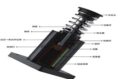
Buffer is essentially an energy dissipation device. Taking the common spring buffer as an example, it follows Hooke’s law. When external impact forces act on the spring buffer, the spring will undergo elastic deformation. In this process, the kinetic energy brought by the impact is converted into the elastic potential energy of the spring. The spring disperses the impact force in time and space through its own expansion and contraction. For example, in an elevator system, when the elevator car unexpectedly loses control and falls, the bottom spring buffer will be compressed. During the compression process, the spring gradually absorbs the kinetic energy of the car falling, avoiding instantaneous rigid collisions between the car and the ground, thereby protecting the safety of personnel and equipment inside the car.
Hydraulic buffers utilize the principle of viscous damping of liquids. When the piston rod is impacted, hydraulic oil flows through the small holes or gaps inside the buffer, generating damping force. This damping force is related to the movement speed of the piston rod, and the faster the speed, the greater the damping force. The impact energy is converted into thermal energy during the flow friction process of hydraulic oil, and then dissipated. At the end of some high-speed automated robotic arms, hydraulic buffers are often installed. When the robotic arm quickly moves to the target position to grab or place an object, the hydraulic buffer can smoothly absorb the remaining kinetic energy, prevent the object from being damaged due to collision, and also protect the joints and transmission components of the robotic arm.
On the other hand, the working principle of the limiter is based on position detection and signal control. Mechanical limiters usually rely on the contact of mechanical structures to trigger. For example, a travel switch has a movable mechanical contact. When the moving parts move to the set position, they will touch the contact of the travel switch, causing the internal circuit to change on and off, thereby emitting a limit signal. Like the cranes in the factory, travel switches are installed at both ends of the track. When the crane is about to reach the end of the track, touching the travel switch will stop the crane from running, preventing it from derailing the track and causing accidents.
The photoelectric limiter utilizes the characteristics of light to detect position. It consists of a light emitter and a light receiver. When an object blocks the light from the emitter to the receiver, the light receiver cannot receive the light signal and triggers the circuit to emit a limit signal. On automated assembly lines, photoelectric limiters are often used for product position detection. When the product moves to a specific position and blocks the light, the photoelectric limiter can accurately detect it, thereby controlling the running rhythm of the assembly line and ensuring the precise processing of the product at each workstation.
In summary, the buffer focuses on the conversion and absorption of energy to cope with dynamic impact forces; The limiter focuses on precise position detection and signal triggering, ensuring that the moving parts of the equipment move within the set range. The two principles are different, but they work together to ensure the normal operation of the equipment.
telephone:025-52791167,52791168
Fax:025-52791169
Phone :13390905858
mailbox:njxj888@163.com skype:yluedq
Address:Jiangning Shuanglong Avenue No.1222 Nanjing, Jiangsu. China P.O. 211100